Modeling Tips
This page collects practical tips for preparing a device mesh set and inspecting the result. It supports Add a Device, which covers the device XML and the YAML config. For assembly-to-MJCF utilities that are under development, see the modeling-tools repository. For the MuJoCo XML format, see the MuJoCo documentation.
What you need
- A 3D model of your device. The mechanism you want to simulate.
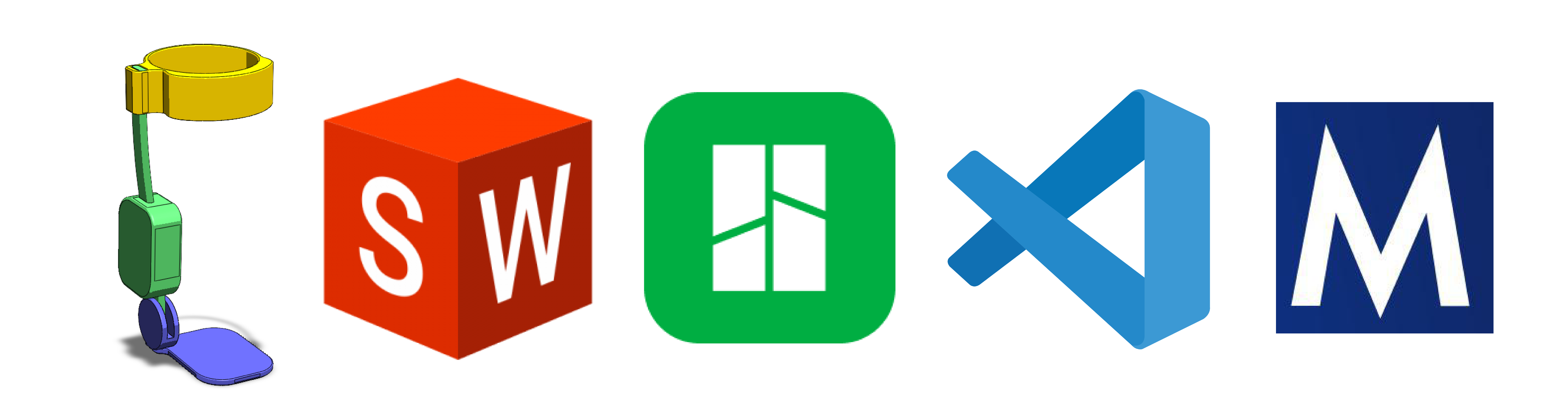
- CAD software. A program of your choice, such as SolidWorks or Fusion 360.
- A slicer (optional). A slicer such as Bambu Studio or PrusaSlicer helps with quick transforms of
.stlfiles. - An XML editor. A text editor or IDE, such as VS Code.
- The MuJoCo visualizer. The standalone
simulatetool from the MuJoCo releases.
Prepare the meshes
Simplify the meshes
Group the connected parts of your device that do not move relative to each other. Export each such group as a single .stl file. This reduces the number of components that you import, define, and position, and it keeps the model accurate.
Check the reference frames
Confirm the origin and the axes of each component in your CAD software before you export. A correct frame at export time saves a lot of adjustment later. A slicer is useful for quick translations and rotations of an .stl file.
Scale to model units
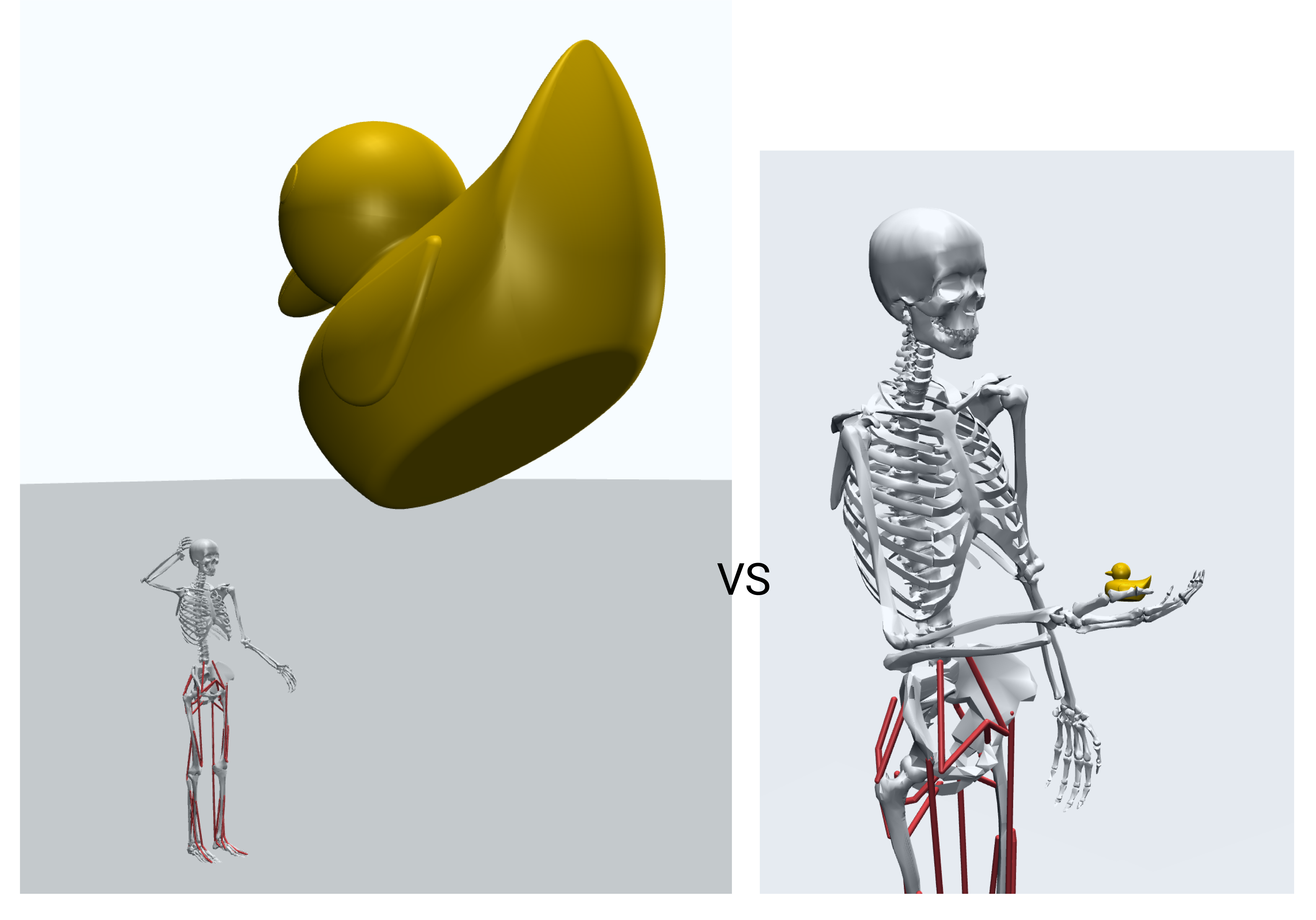
The myo_sim models use meters. CAD software often exports in millimeters. If your device is in millimeters, scale it by 0.001 to convert it to meters. A device at the wrong scale looks far too large or far too small when it attaches.
The pipeline reads the pos and quat of each device body in the frame of its parent MSK body, not in the world frame. So orient each mesh to sit correctly against its attachment body, then fine-tune the placement with pos and quat on the attachment. See Add a Device. The figure below shows a part defined at world scale (left) against the same part scaled and placed in the model frame on the model’s hand (right).
Inspect in the MuJoCo visualizer
The visualizer is your primary tool for inspecting and debugging a model.
Reset to a keyframe first. When you load or reload a model, reset it to a keyframe pose with the Simulation -> Key menu. The pose at load time is not the intended pose.
Useful menus
- Simulation -> Reset: reset the model to a selected keyframe pose.
- Simulation -> Reload: reload the XML file to reflect saved changes.
- Simulation -> Run/Pause: toggle the physics. Pause it while you edit.
- Simulation -> Copy Pose: copy the current
qposandqvelto the clipboard. This is useful for updating a keyframe after you pose the model. - Rendering -> Inertia: render the inertial box for every body.
- Rendering -> Contact Point / Contact Force: show contact locations and forces.
- Rendering -> Static Body: hide or show non-moving bodies, such as the ground.
- Rendering -> Group Enable: toggle the visibility of geom and site groups. The foot and toe touch-sensor sites are in
Site groups -> "Site 3".
Viewer hotkeys
- Space: play or pause the simulation.
- + / -: speed up or slow down.
- Left / Right arrow: step back or forward.
- [ ]: cycle the camera.
- Esc: free camera.
- F1: help. F2: info. F5: full screen.
- Scroll or middle drag: zoom. Left drag: orbit. Shift + right drag: pan.
- Double-click: select. Page Up: select the parent body.
- Ctrl + drag: rotate the selected object. Ctrl + right drag: translate it.
Check contacts and sensors
Verify how the model touches its environment. Use the Contact Point and Contact Force render options for this.
- Self-contact. If the model collides with itself, add a
contactentry to the device config to exclude the collision between specific geoms. See Device Configuration. - Unexpected forces. If the model generates surprising forces, adjust the pose. A
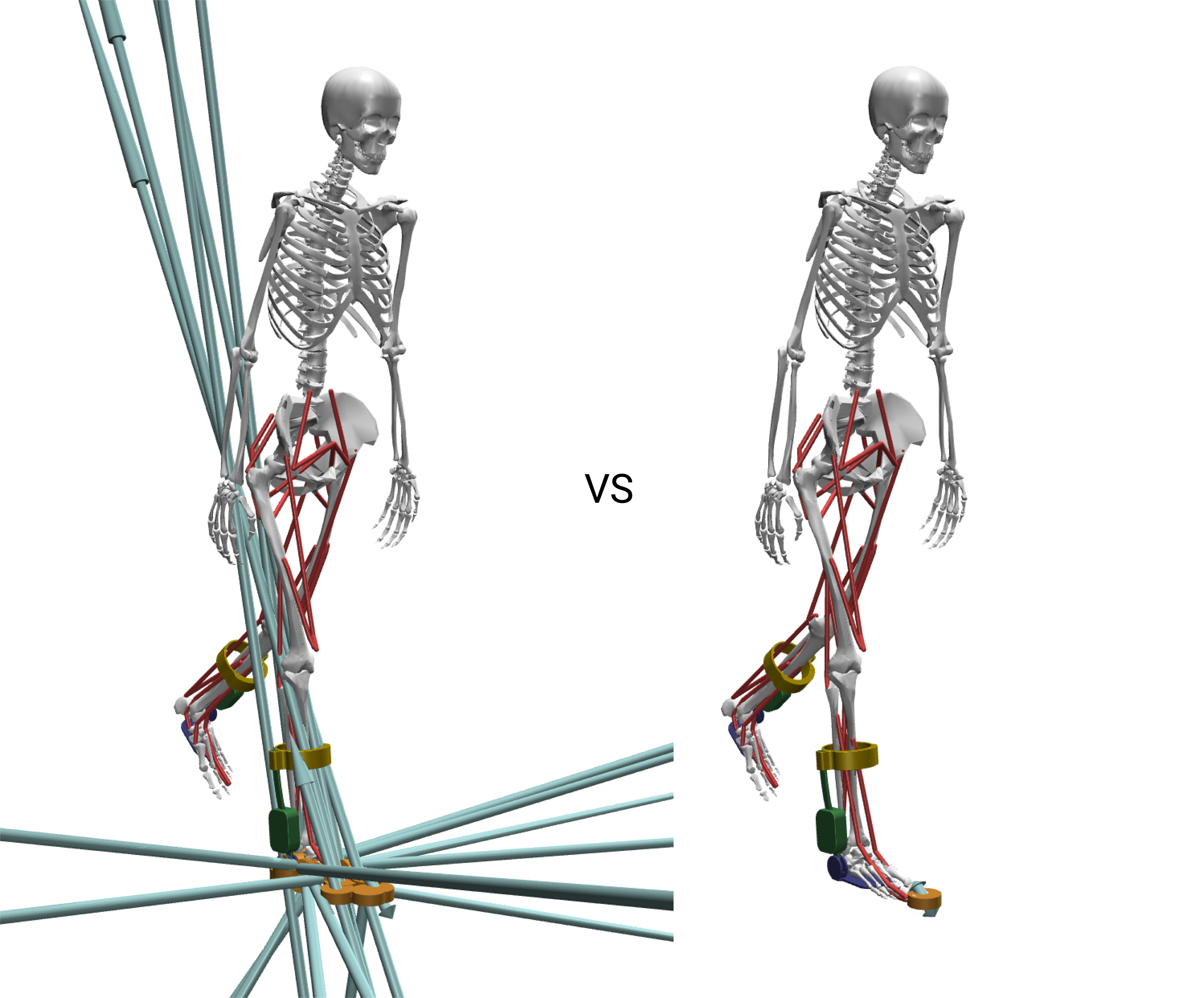
pelvis_tythat is too low pushes the model into the terrain and creates large contacts. - Devices on the feet. A shoe or a foot device changes the ground clearance. Set the model’s initial height (
pelvis_ty) with akeyframe_overridesentry so the model does not start inside the terrain. Re-declare the foot touch sensors (r_foot,r_toes) against sites that match the new geometry with asensorsentry. Those sensors read the touch sitesr_foot_touchandr_toes_touchby default.
See also
- Add a Device: the device XML and the YAML config.
- Device Configuration: the config sections for contacts, sensors, and keyframes.
- modeling-tools repository: assembly-to-MJCF utilities under development.